2700 E Magnolia Dr. Gilbert AZ 85298
Phone 602 995 5311
[ Home ]
[ Products ]
[ Ordering ]
[ Shipping ]
[ About Us ]
[ Contact Us ]
[ Back ]
[ Home ]
[ Products ]
[ Ordering ]
[ Shipping ]
[ About Us ]
[ Contact Us ]
[ Back ]
Search the Store by Description, Year, Model or
SEARCH BY STUDEBAKER PART NUMBER
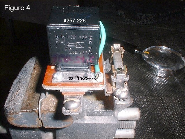
The relay
| Radio Shack # |
275-226 |
| Coil Voltage |
12 V |
| Pull-in Voltage |
6V |
| Drop-out Voltage |
3.6 V |
| Coil Resistance |
66 Ohms |
| Nominal Current |
160 mA |
| SPST Contacts |
30 A at 12 VDC |
| Pin Out |
|
Tools Required
You will need a heavy duty soldering iron for this project. I purchased one used for
stain glass and it works marvelously. A Dremel tool with a wire brush attachment is great
for cleaning up parts. If you don't have a Dremel, get one, best tool I own. An ohm meter
is good also but a continuity checker probe will work just as well.
The Rebuild,
I purchased a foot of #10 gauge solid wire from Home Depot to carry the major current
from the battery to the solenoid. I used #18 braided wire for the connections from the
kickdown switch terminal & the ignition switch terminal. Since these #18 wires won't
be carrying much juice, I used .5" female crimp-on connectors and soldered the
connector to the wire for better contact. I could then slide these connectors on/off the
relay pins getting them out of the way for soldering the #10 gauge wires. It is important
to note the #10 solid copper wire should be as short as possible to minimize the
resistance and voltage drop in the relay.
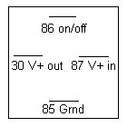
From the Studebaker Shop Manual it shows the following 4 connections to the OD Relay.
In testing this circuit I did the last test in the OD relay trouble shooting guide where
you ground out the OD governor wire, turn the car key on, and check for current on the
unconnected SOL terminal. In this configuration, you should be reading 6 volts (the car
isn't running right?) going into the 20 amp fuse, 6 volts coming out of the 20 amp fuse,
and about 5.8 volts coming out on the SOL terminal. The table below summarizes the
connections
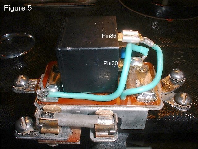
| BAT |
#10 gauge Black Wire |
Connects to Pin#87 on relay |
| SOL |
#10 gauge Red Wire |
Connects to Pin#30 on relay |
| IGN |
#16 gauge Red/Yellow Wire |
Connects to Pin#86 on relay |
| THSW |
#16 gauge Green Wire |
Connects to Pin#85 on relay |
You will have to remove the top cover of the relay from the base. It is held in by four
crimps in the cover at the corners. After the top cover has been removed, clean out the
old relay coil and remove any pieces you can. Next spray the unit with carb cleaner or
brake cleaner to get some of the gunk off. I used my Dremel and the mini wire brush to
make the metal all nice and shiny.
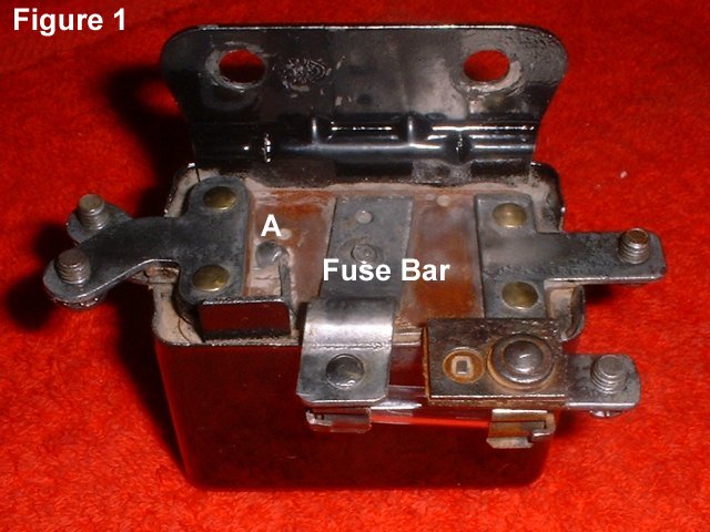
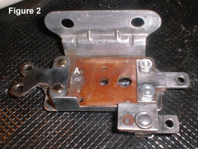
In Fig.1 below is a bottom view of the Old Original Stock piece. Fig.2 shows what I had
to work with from the prior rebuild. I would suggest you strip the base of your core down
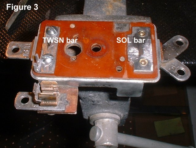
as far as possible. When completed you should have something like Fig.3 to start work
with.
Wire #1 and #2 - Cut two 5 inch pieces of #16 gauge wire and solder the female crimp
connectors to one end of each. Slide the connectors onto the relay pins #85 and #86 for
trial fitting, leave them long for now. The new relay case will need the mounting tab
trimmed to fit flush onto the base of the relay core.
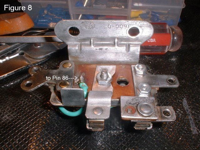
Wire #1 from pin #86 will pass through a hole in the core base and attach at the bottom
of the base to the IGN terminal (point A in Fig 1 & Fig 2).
Wire #2 from pin #85 will pass under the new relay and attach to the core base at the
TWSN terminal (point A in fig 3).
Wire #3 - Cut a 2 inch piece of the #10 solid wire and bend a 90 degree .5 inch foot at
one end. Flatten this end out on your vise so we get more of a footprint. Enlarge the
existing hole in the new relay pin #30 to accept the straight end of this piece. Trial fit
this piece between the SOL pad (point B in Fig 3). Get an old 120vac power cord and strip
off a piece of insulation to cover this wire from point B to pin #30.
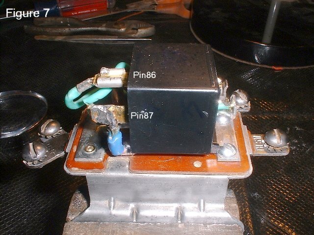
Wire #4 - Cut a 4 inch piece of the #10 solid wire solder one end to pin #87 on the
relay. This piece must connect down stream of the 20 amp fuse. Since my core was already
rebuilt, my instructions would be different. Find the point on the top of the core base
that is connected to the fuse bar (point B in Fig 1). This is where you will need to
solder this piece. Trial fit the piece, then cover with old power core insulation, and
solder to core base.
Connection #1 - Now solder wire #4 to the point found above. Solder the other end to
relay pin #87, making our first connection.
Connection #2 - Next solder wire #3 to the SOL pad (point B Fig 3). Slip the insulation
on wire #3, seat the new relay to the core base, route wire #2 to the TWSN terminal (point
A in fig 3). Solder wire #3 to terminal #30 on the new relay.
Connection #3 - Now attach wire #2 to pin #85 and solder the other end to the TWSN
terminal (point A in fig 3). Trim off excess before soldering.
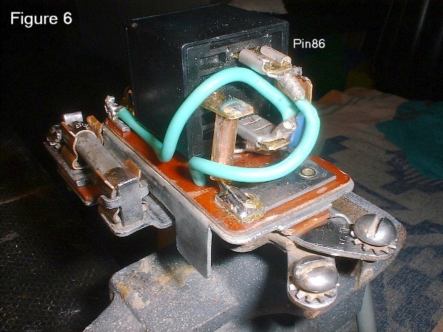
Connection #4 - Finally, attach wire #1 to pin #86, pass through the core base, and
solder the other end to the IGN terminal (point A in Fig 1 & Fig 2). Trim to fit and
solder.
Now test all four wires for continuity from the relay, out to the core base. If you did
it correctly, you should be able to replace the top cover of the relay to the base, hiding
all your nice work. The finished product should look something like below
Testing
Put the relay back into the circuit, connecting the wires to all but the SOL terminal.
Ground out the OD governor wire at the lock out relay, turn the car key on, and check for
current on the unconnected SOL terminal. In this configuration, you should be reading 6
volts (the cars is not running right?) going into the 20 amp fuse, 6 volts coming out of
the 20 amp fuse, and about 5.8 volts coming out on the SOL terminal.